Project Overview
Since the summer of 2025, me and one of my colleagues have been developing and researching out take on a Parallel-Axis Tripteron. Through this project, we are experiencing a WPI-specific program called an Independent Study. This program has allowed me and my colleague to learn about linkage analysis from WPI professor Mustapha S. Fofana.
By the end of this project, we hope to accomplish a fully iterated version of the prototype we built during summertime, alongside gaining a mastery of linkages.
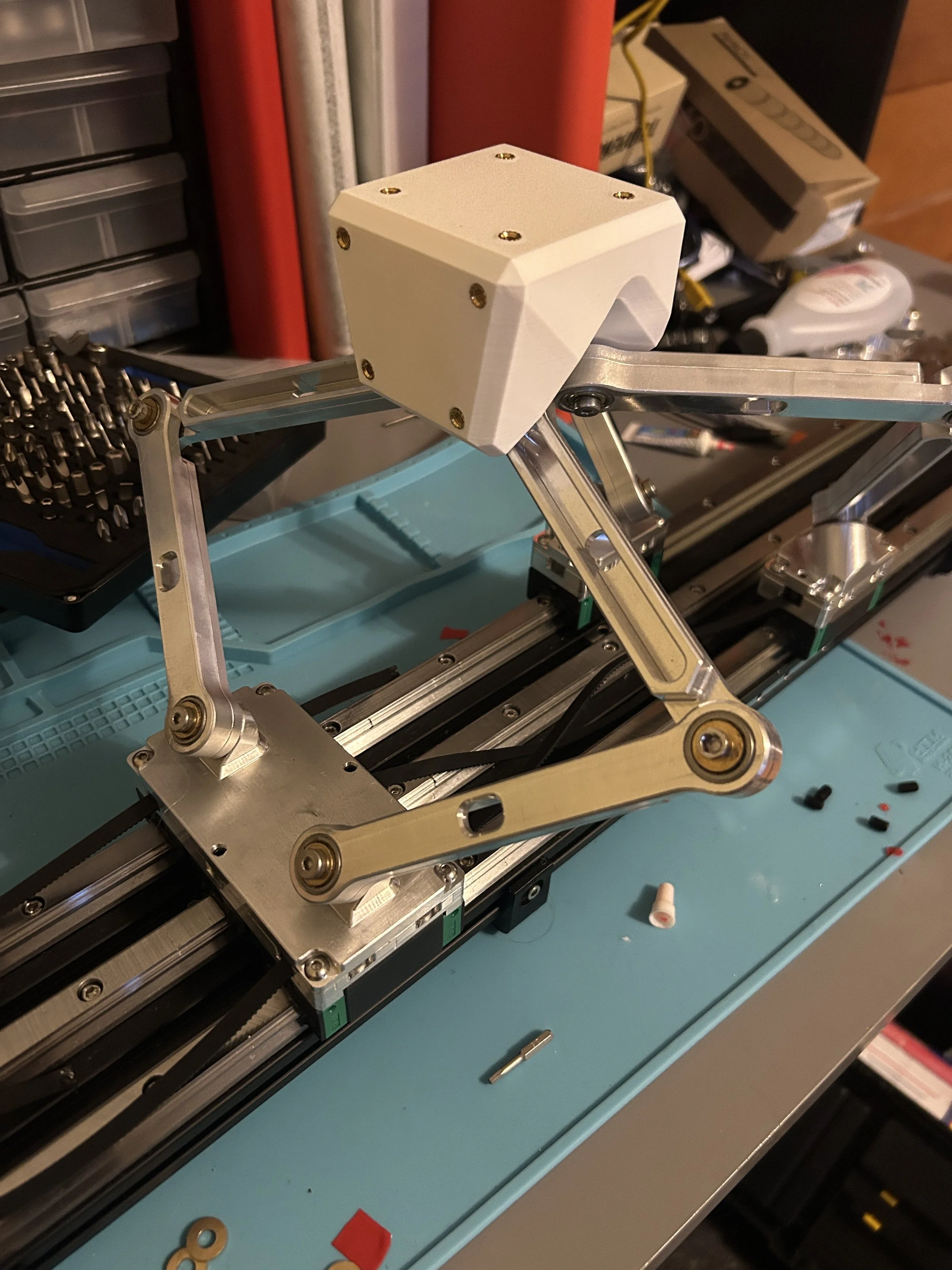
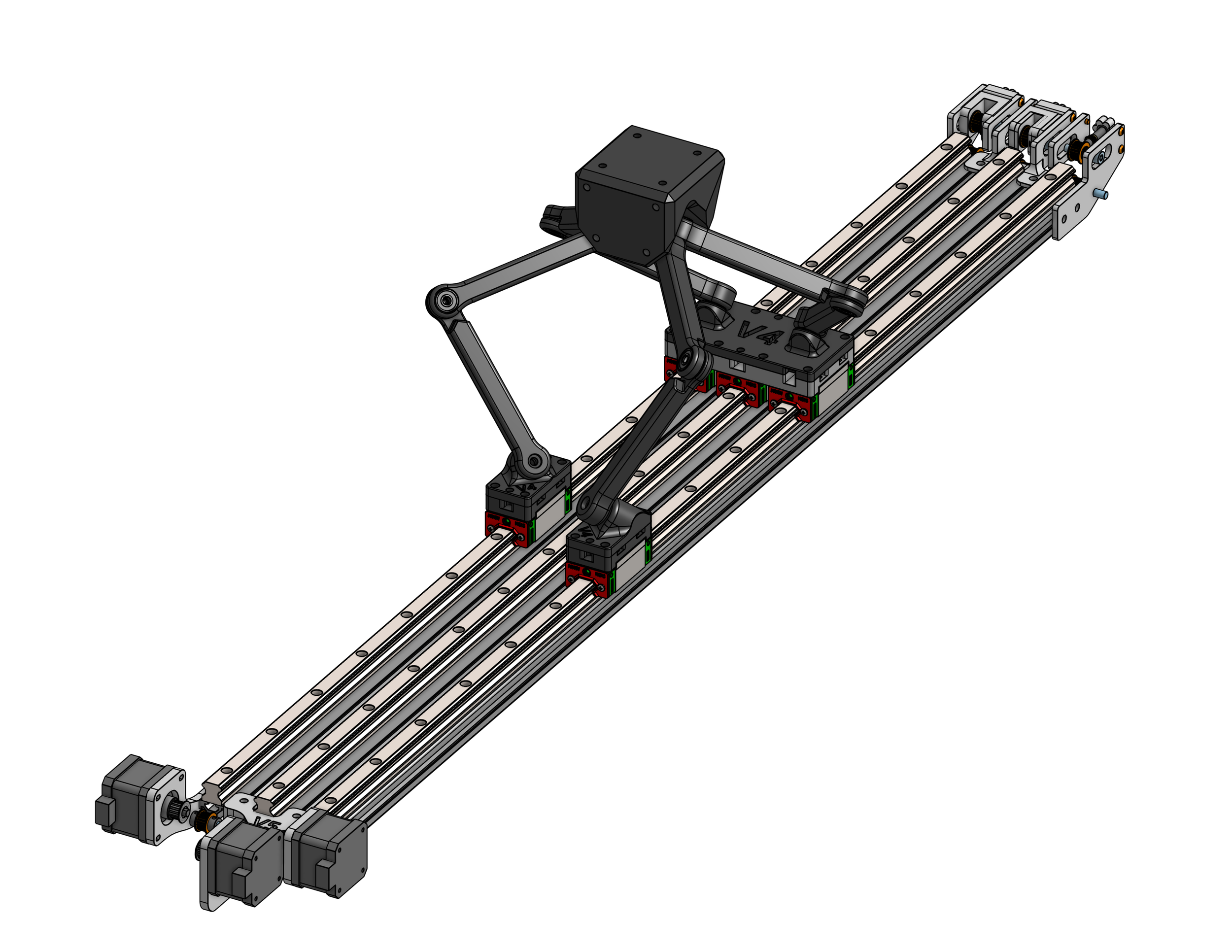
A Parallel-Axis Tripteron is a robotic system that is able to acquire precise 3D positional movement. This works by having 3 independent motors driving parallel linear guides, each with their own linkage system connecting to an output head.
A benefit to this linear motion system is the benefits of outputted cartesian motion, while not requiring the addition of a z-axis gantry
Summer Prototyping
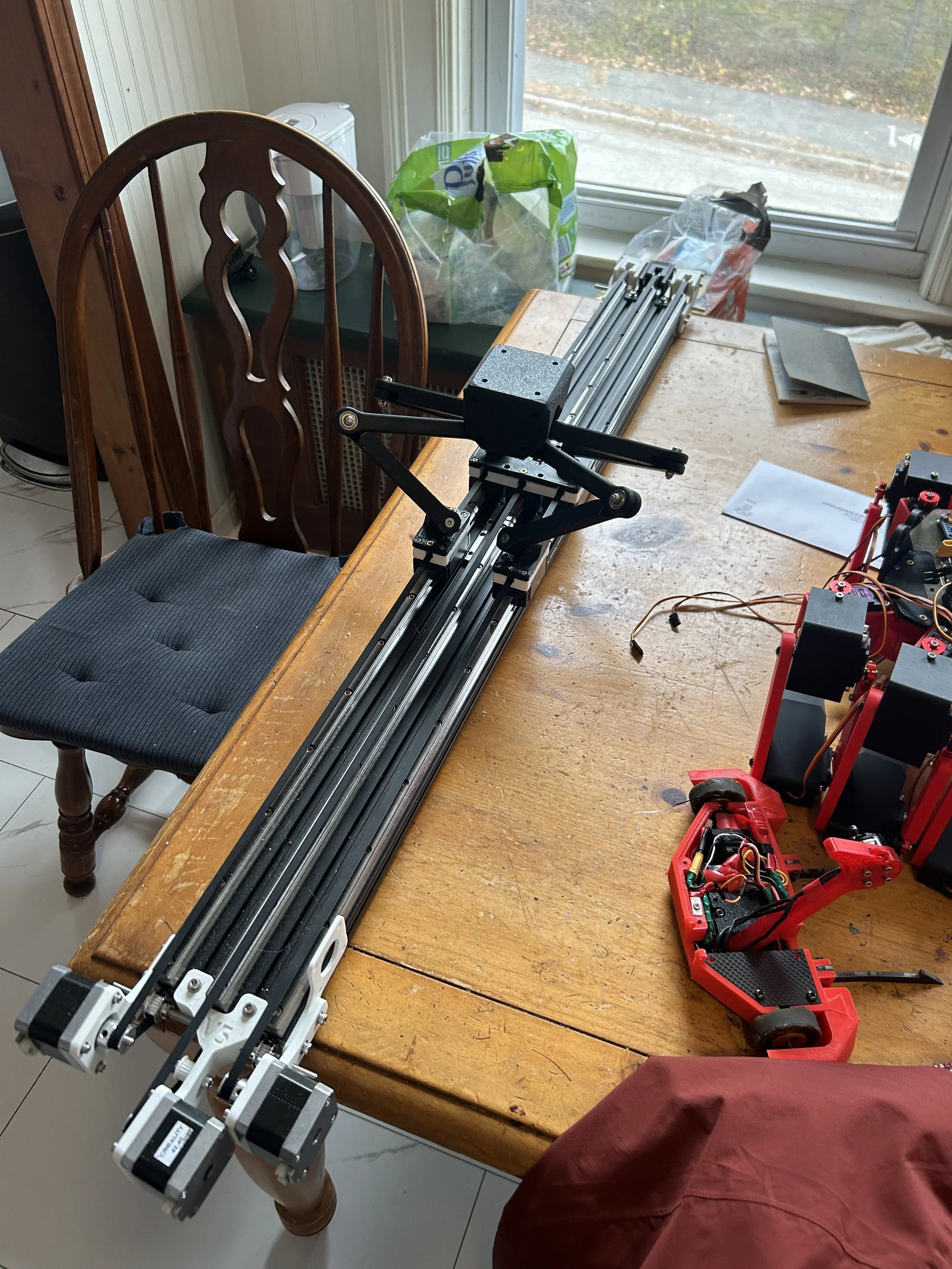
Throughout the summer, me and my colleague worked together to develop a fully finished prototype, with all custom parts being 3D Printed.
These efforts got the ball rolling on many things that we plan on implementing for the second version. Here is a run-down on the big subsystems of the project during the prototyping stage
3D Movement
How we attain 3D cartesian movement from the Tripteron is through these system of linkages (shown in purple). Based on how the linear bearings, shown in blue and gray, move independently from one another, the Tripteron head (shown in green) will sway linearly in any 3D motion. This motion is solely dependent on the combination of the 3 linear bearings

Linear Motion & Belting
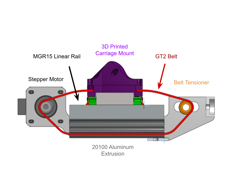
To drive each linear bearing, I used a very similar setup of electronic control to how CNC machines and 3D printers do it due to their nature of executing precise motion. Each linear rail would have a Stepper Motor, Belt Tensioner and Linear Bearing (HGH15 Bearing) driven by a GT2 Belt. Since we use a slotted piece of aluminum (20100 Slotted Aluminum Extrusion) we are able to path the belt through the bottom slot.
Electrical & Controls
For prototyping electronics, we utilized an Arduino Uno with a CNC Shield, which utilized A4988 Stepper Drivers.
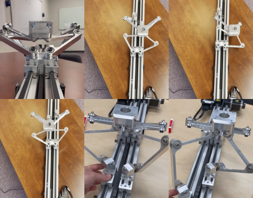
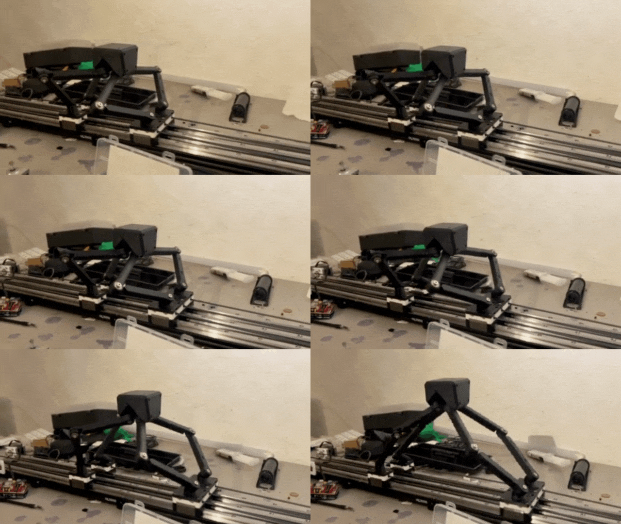
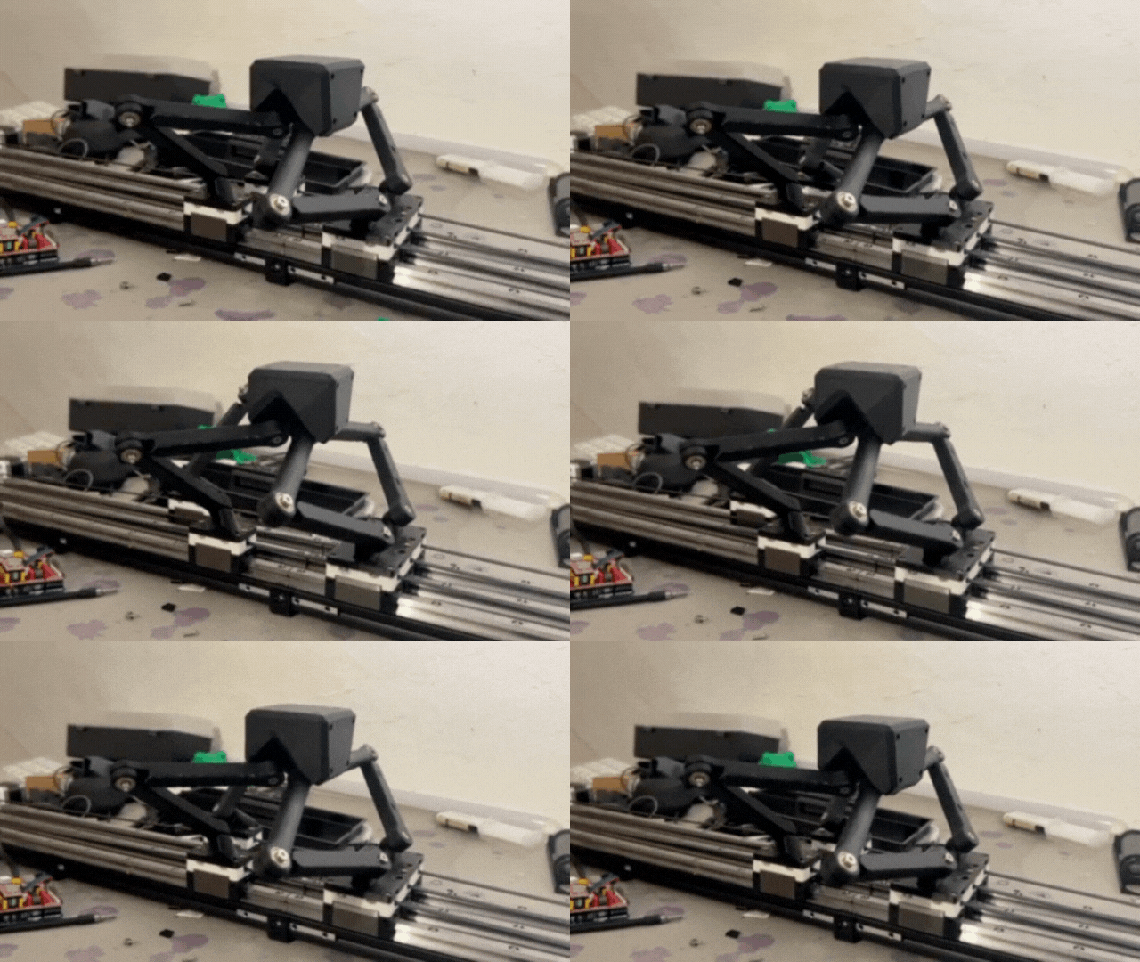
By the end of summer, we were able to successfully implement some basic 1-2 motor controls through a gcode sending app like Universal Gcode Sender. Here are some clips of the Tripteron moving.
Version 2
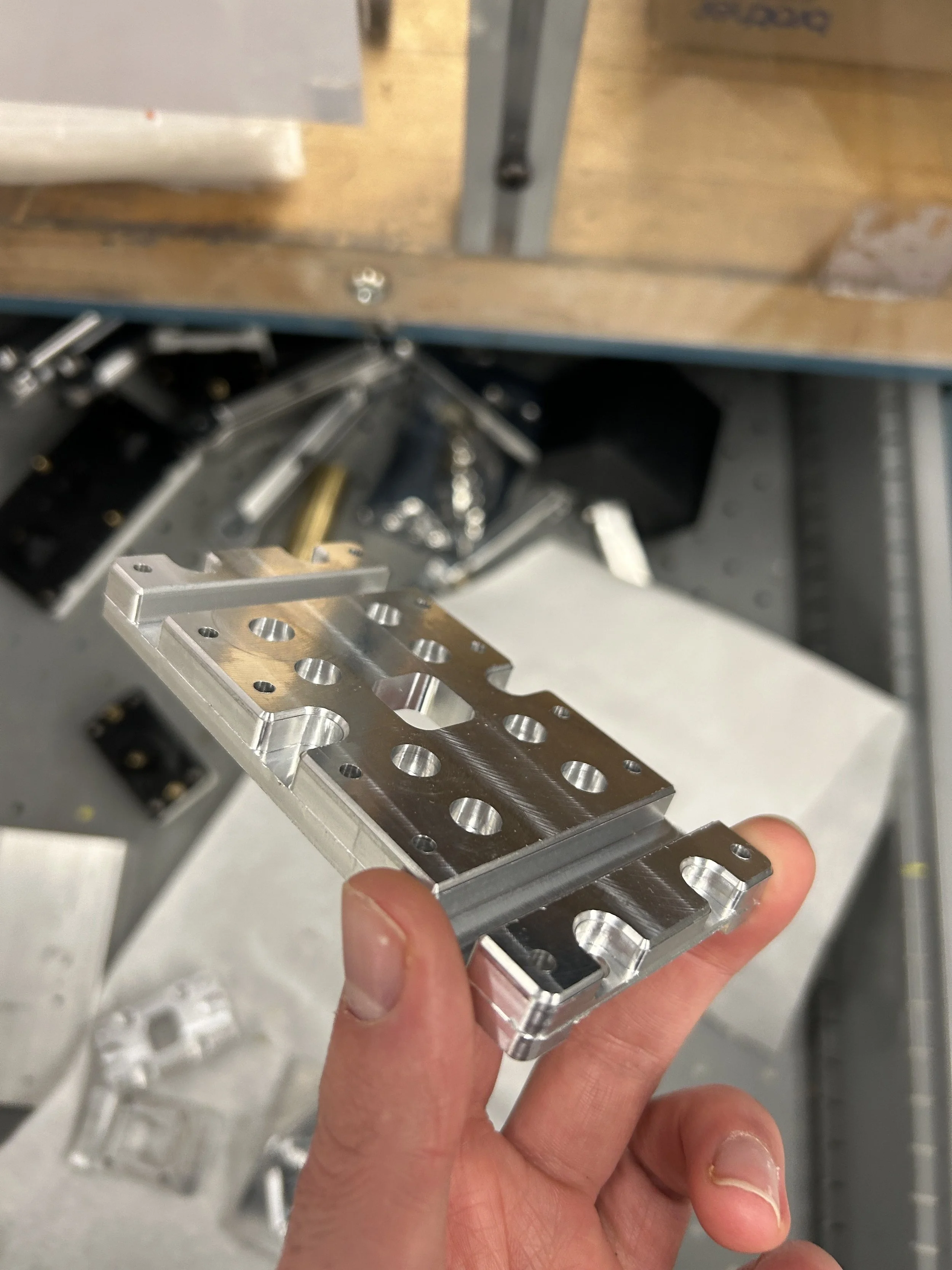
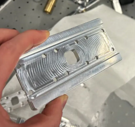
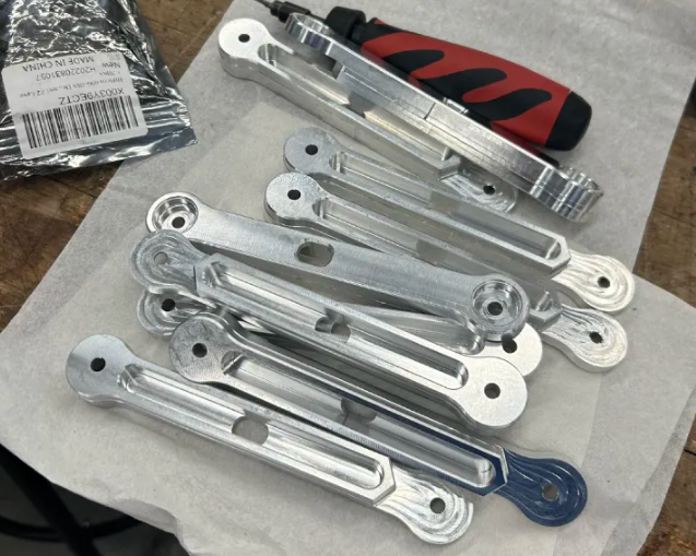
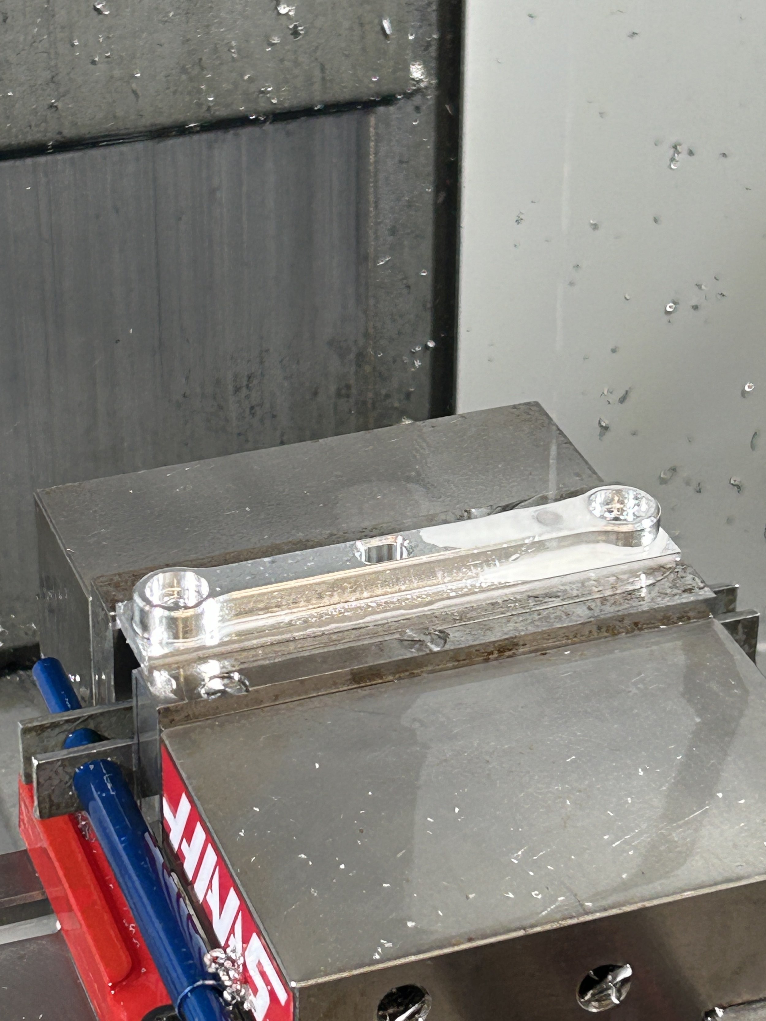
Throughout the school year, me and my colleague started preparing for material upgrades for many portions of the Tripteron. This includes CNC Machining the linkages and linear bearing mounts out of 6061 Aluminum, as well as water jet cutting stepper motor and belt tensioner mounts out of Stainless Steel.
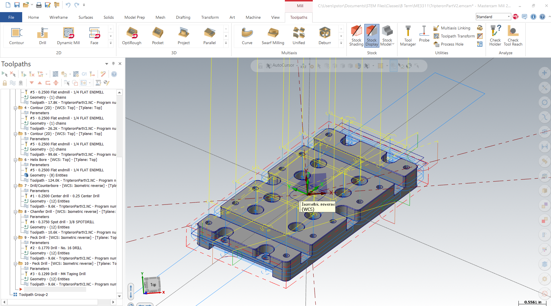
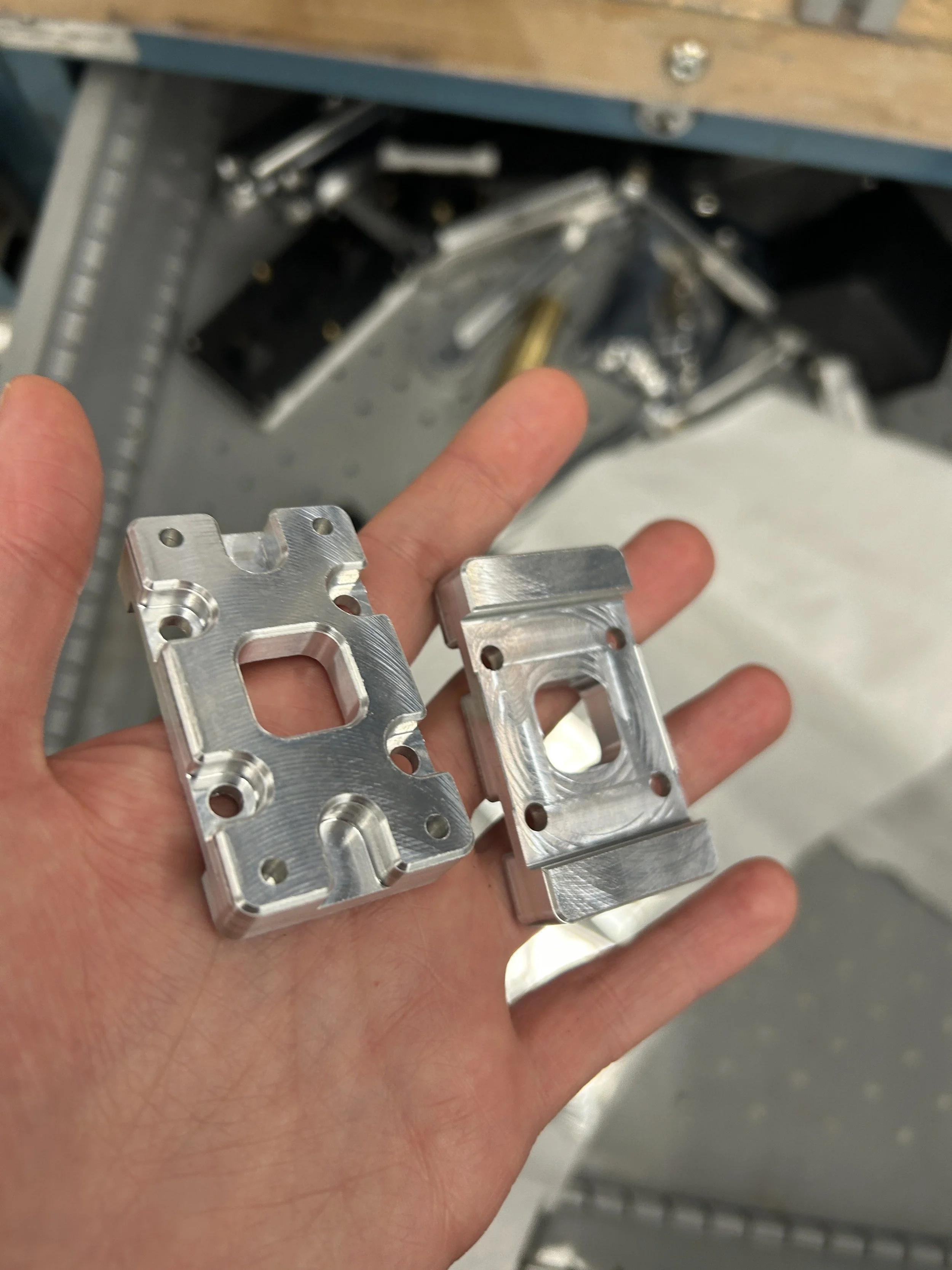
Shown below is the CAM of one of the machined linear bearing mounts, as well as images of some of the stainless steel parts already fabricated.

To divide up work based on subassembly, my colleague handled the CAD, CAM and manufacturing of each linkage. Here are some snippets of the linkages.
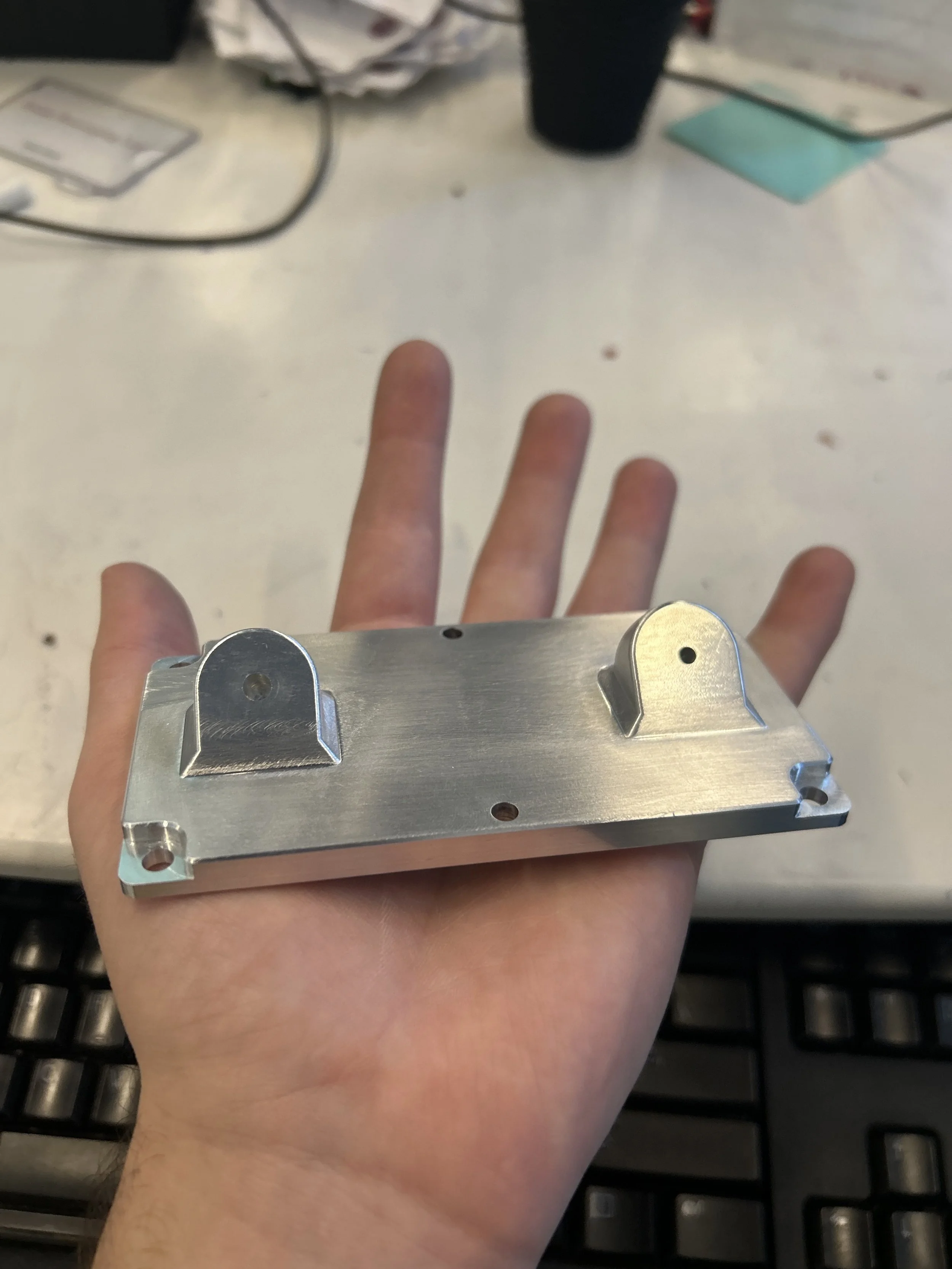
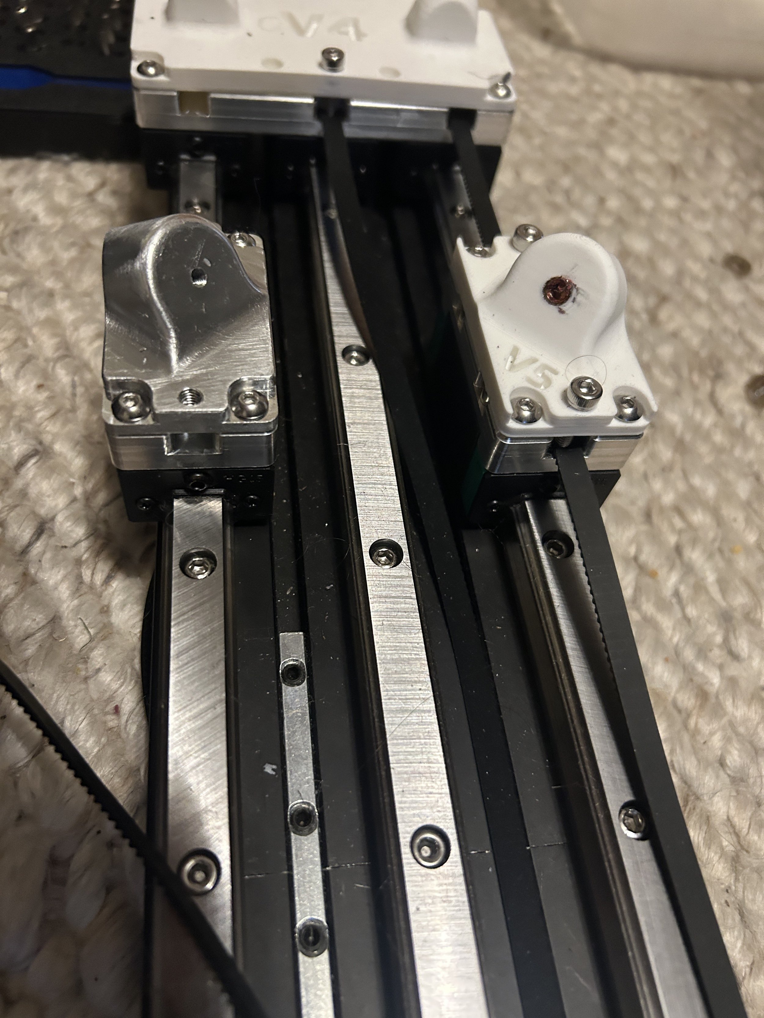
Additionally, the top portion of each linear bearing mount was outsourced to JLCPCB. These parts were made out of 6061 Aluminum, and needed to be machined via 5-axis CNC capabilities in order to acquire each custom angle.
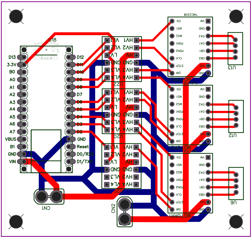
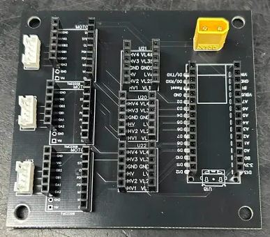
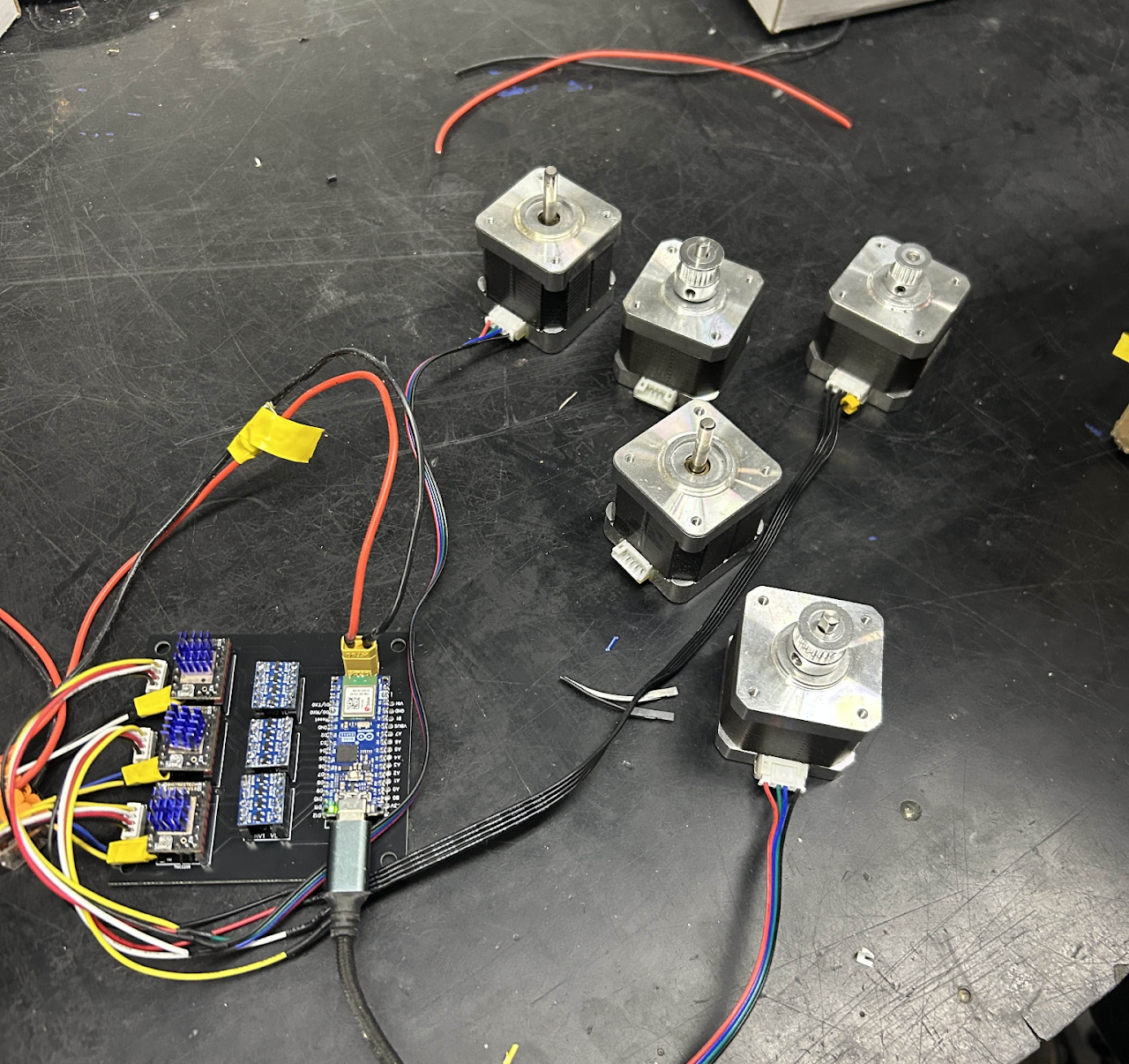
Through multiple iterations of circuit design, I went with this PCB design. This circuit board uses TMC2208 stepper motor drivers. The reasoning behind this design decision was due to the stepper driver’s due to its smooth sinusoidal current waveform, which results in dampened vibrations and noise reduction. Additionally an Arduino Nano ESP32 due to its processing power.