Note: This is an ongoing project that will be updated as significant progress is made in the future
Project Overview
Worcester Polytechnic Institute’s Mechanical Engineering program has this lab-based class called Engineering Experimentation. It’s main focus is on microcontrollers and teaching students how to utilize devices like Raspberry Pi and Arduino. What the class also has is an open-ended final project where you work either by yourself or with a group partner to develop a product. Through this project, I decided to fully develop a 6-legged walking robot on my own.
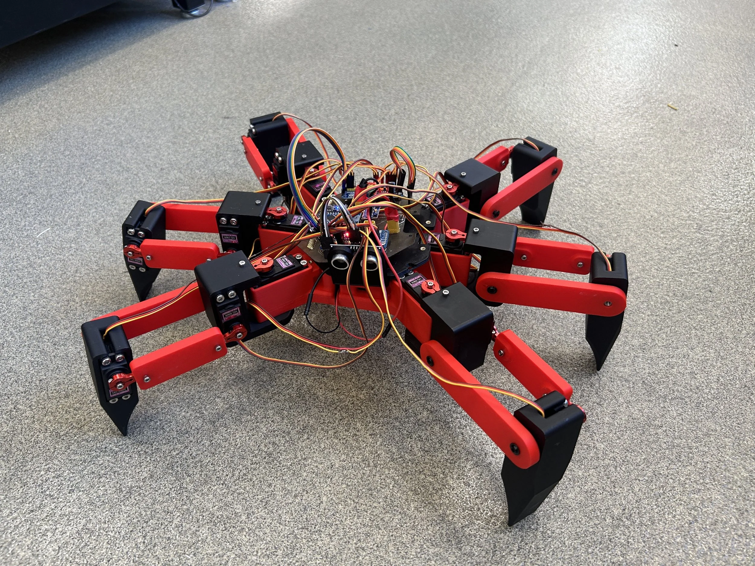
A walker robot is a robot that utilizes 2-3 degrees of freedom per leg module to execute a walking motion for movement (think of how a crab or spider works)
A benefit of designing these robotic systems is that it greatly improves your sense for mechatronic based systems, your controls engineering skills, and your Design for Assembly skills due to how much electronics there are to factor
GIF Provided by roboticgizmos.com
Here is the finished CAD for the first version of my walker. All red and black parts are 3D printed out of PLA+ and Super PLA+ due to their strength and resistance to impact. Each MG996R Servo Motor has been dual supported through the use of threaded standoffs, heat set inserts, bearings, and button-head screws


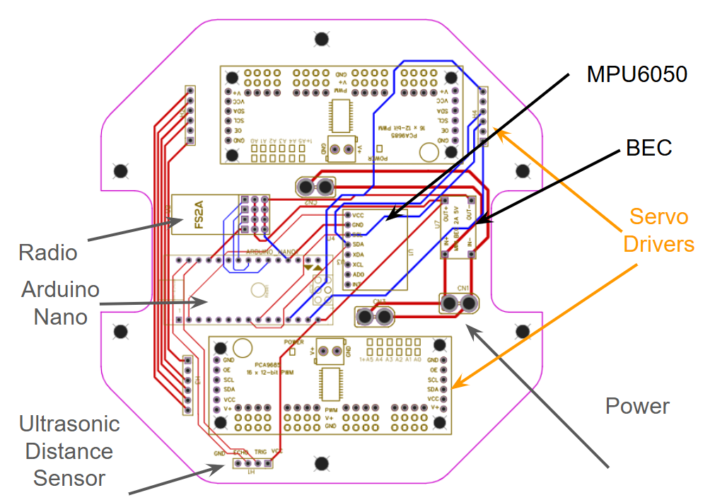
For this project, I decided to utilize a Printed Circuit Board. A downside to making a walker is that there are a lot of electronics to factor in. So having a board that acts as more compact wiring alongside holding all electronics in place makes a PCB vital to this project
Recently I became a Lab Assistant for my WPI’s makerspace. The Prototyping Lab that WPI runs has a PCB Fabrication device, so we used this circuit board as a means of training me to know how to use the machine
I am able to control the walker’s movement through the use of an RC transmitter and receiver sold by Flysky. I am well experienced with RC devices, having used them in combat robotics, and felt like that was a great way to introduce myself to control systems. Here is a video showing a leg motion sequence
Version 2 Revisions
Even though the class is over, there are some aspects of the walker that I would like a second version to resolve.
The first of these improvements is a more power-dense power supply. I have been calculating what would be the necessary battery size and it seems like this would make for the best option.
The second of these improvements includes a lighter frame. There were many instances where the walker would remain off balance due to how much weight was used for a billet 3D printed chassis.
